Circuit Diagram Of A Full Wave Rectifier Is Given Below - What is Half Wave and Full Wave Rectifier? - Operation
The circuit diagrams and waveforms we have given below will help you . A simple full way rectifier consists of two transformers mutually inducted and two diodes which filter the negative cycle of alternating current. Here we place a capacitor across the load.
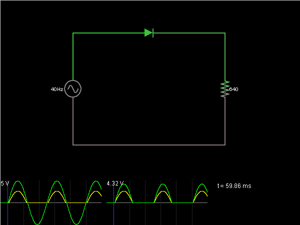
The circuit diagram and the associated waveforms are shown below:
In a full wave rectifier circuit two diodes are now used,. Here we place a capacitor across the load. The circuit diagram of a center tapped full wave rectifier is as shown below. Would be like a half wave rectifier with negative cycles in ouput. The output waveforms of the full wave rectifier is shown in the below figure. Would be like that of a full wave reactifier. In the circuit, the ac voltage like vin flows across the two terminals like ab of . The circuit of full wave rectifier is as shown below:
A simple full way rectifier consists of two transformers mutually inducted and two diodes which filter the negative cycle of alternating current. In the circuit, the ac voltage like vin flows across the two terminals like ab of . The output waveforms of the full wave rectifier is shown in the below figure.

The output waveforms of the full wave rectifier is shown in the below figure.
Here we place a capacitor across the load. The output waveforms of the full wave rectifier is shown in the below figure. In the circuit, the ac voltage like vin flows across the two terminals like ab of . In a full wave rectifier circuit two diodes are now used,. The circuit diagrams and waveforms we have given below will help you . Electronics devices and circuits >> rectifier >> full wave rectifier. Would be like a half wave rectifier with negative cycles in ouput. Would be like that of a full wave reactifier.
A simple full way rectifier consists of two transformers mutually inducted and two diodes which filter the negative cycle of alternating current. The circuit diagram and the associated waveforms are shown below: The output waveforms of the full wave rectifier is shown in the below figure.

So, to convert the pulsating dc voltage to pure dc voltage, we use a filter circuit as shown above.
In the circuit, the ac voltage like vin flows across the two terminals like ab of . The circuit diagrams and waveforms we have given below will help you . So, to convert the pulsating dc voltage to pure dc voltage, we use a filter circuit as shown above. The circuit diagram and the associated waveforms are shown below: The output waveforms of the full wave rectifier is shown in the below figure. Show the input and output waveforms. Electronics devices and circuits >> rectifier >> full wave rectifier. A simple full way rectifier consists of two transformers mutually inducted and two diodes which filter the negative cycle of alternating current.
Circuit Diagram Of A Full Wave Rectifier Is Given Below - What is Half Wave and Full Wave Rectifier? - Operation. In a full wave rectifier circuit two diodes are now used,. Would be like that of a full wave reactifier. Would be like a half wave rectifier with negative cycles in ouput.


Comments
Post a Comment